
Global power systems are becoming more demanding. The International Energy Agency’s Electricity 2024 report projects average global electricity demand growth of 3.4% annually from 2024 to 2026. More load means greater pressure on distribution equipment, especially in factories, data centers, hospitals, and infrastructure projects.
An ACB Breaker offers practical protection for these high-current environments. Designed under the IEC 60947-2 low-voltage standard, it can interrupt severe fault currents while supporting adjustable long-time, short-time, instantaneous, and earth-fault protection. Engineers can coordinate these settings with downstream molded-case circuit breakers. That coordination helps isolate a fault without shutting down an entire facility. In a switchboard, a withdrawable ACB can also be tested or serviced more efficiently. Operators can inspect the contacts, trip unit, and connection position with clearer physical control.
The details matter.
Reports from the International Energy Agency and the International Electrotechnical Commission show why reliability, maintainability, and standardized testing remain central to modern power protection. An ACB is not simply a larger circuit breaker. Its value depends on correct fault calculations, selective coordination, routine inspection, and properly trained personnel. Poor settings can create nuisance trips or delayed disconnection. That risk is easy to underestimate. Real installations also differ by voltage, short-circuit level, ambient temperature, and operational duty. Therefore, choosing an ACB Breaker requires more than comparing frame size or breaking capacity. It requires evidence from the site, the protection study, and the manufacturer’s verified performance data.
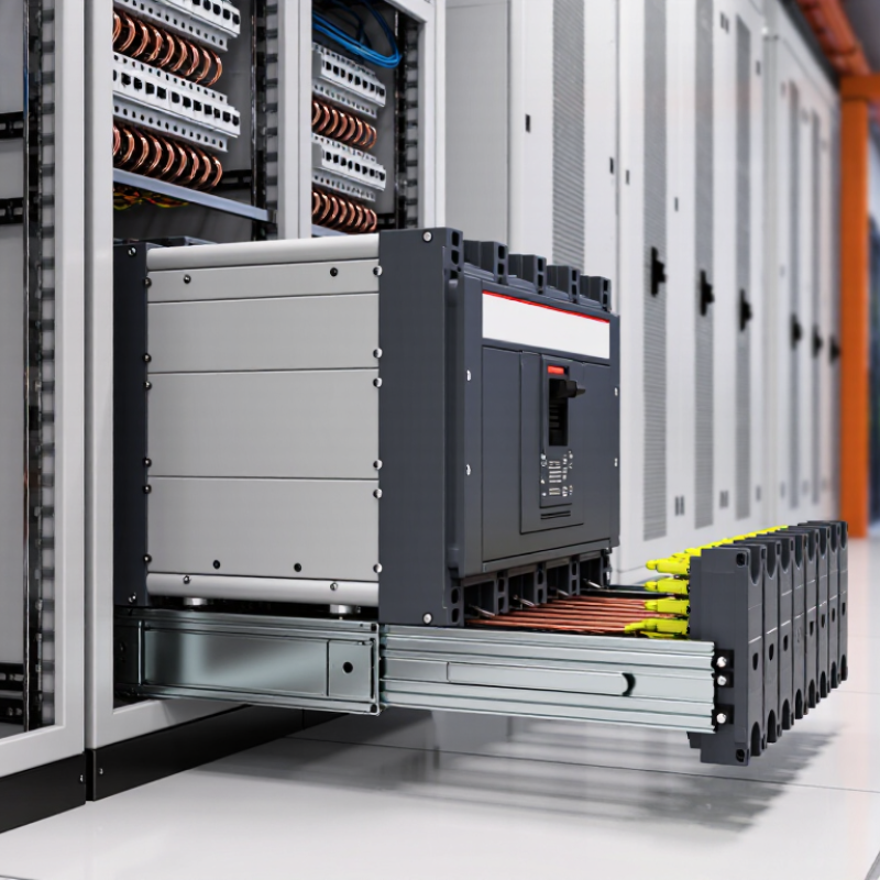
Air circuit breakers protect low-voltage distribution systems with high current demands. They are commonly rated up to 6,300 A and 1,000 V AC. This range suits factories, data centers, transport facilities, and large commercial buildings. An ACB can interrupt fault current, isolate equipment, and support controlled maintenance. Its draw-out design also allows technicians to inspect contacts without removing the complete breaker. In practice, clear labeling matters as much as the interrupting rating. A well-rated breaker still creates risk when installed incorrectly.
Selection should match the system voltage, continuous current, short-circuit level, and coordination plan. Electronic trip units can provide adjustable long-time, short-time, instantaneous, and ground-fault protection. These settings need professional verification, not guesswork. Testing should follow applicable standards, such as IEC 60947-2, local electrical rules, and the equipment maker’s instructions. Field conditions can expose weaknesses that calculations miss. Dust, heat, vibration, and frequent switching may change performance over time.
Tips: Confirm the busbar rating first. Check ambient temperature and enclosure ventilation. Record every protection setting. Test trip functions during planned maintenance. Keep spare control components properly stored. A commissioning report should include measured results, not only signatures. I have seen projects where the breaker was correctly selected, but the cables were not. That detail deserves a second review.
Why Choose an ACB Breaker for Global Power Protection?
In low-voltage networks, an air circuit breaker provides controlled protection for large feeders and switchboards. An ACB built for IEC 60947-2 is tested against demanding short-circuit conditions. The standard evaluates rated performance, interruption behavior, insulation, and operational endurance. Breaking capacities can reach 150 kA in selected LV configurations, offering strong protection near transformers and high-fault industrial supplies. That figure matters when a short circuit releases intense heat, magnetic force, and arc energy within milliseconds. In practical site reviews, engineers examine fault calculations, cable lengths, and upstream transformer impedance before selecting the breaker. The result is better coordination and reduced equipment damage. Real protection starts with verified data.
Engineers should compare Icu, Ics, rated current, and short-time withstand capacity. Icu addresses the maximum fault current the breaker can interrupt under specified conditions. Ics indicates its ability to interrupt service faults while remaining suitable for continued operation. They must also check voltage, frequency, installation altitude, ambient temperature, and enclosure conditions. A breaker may withstand 150 kA in testing, yet the complete assembly still requires proper busbar design and connection torque. Not every installation achieves the published result. Loose connections can become dangerous hot spots. Trip settings deserve careful review because excessive delay increases arc exposure, while overly sensitive settings may cause unnecessary shutdowns. Field measurements often reveal assumptions that drawings hide. High capacity alone does not guarantee dependable protection.
Why Choose an ACB Breaker for Global Power Protection?
Global facilities need protection that isolates faults quickly without shutting down healthy circuits. Selective coordination aims to achieve this balance. In practical designs, a 50–100 ms clearing window can help downstream devices respond before the upstream ACB trips. The target is demanding, not universal.
An ACB supports adjustable long-time, short-time, instantaneous, and ground-fault settings. These functions allow engineers to shape time-current curves around real load conditions. Zone-selective interlocking can further reduce delay during high-current faults. However, settings must reflect cable impedance, transformer data, motor starting current, and available short-circuit current. Guesswork is dangerous.
The International Energy Agency’s Electricity 2024 report estimates data centers used about 460 TWh globally in 2022, with demand potentially exceeding 1,000 TWh by 2026. Uptime Institute’s 2023 Global Data Center Survey reported that 55% of respondents experienced an outage costing more than $100,000. These figures make coordination more than a drafting exercise. It affects uptime and financial exposure. A 50 ms target is not magic. Protection studies, commissioning tests, and periodic reviews still matter. In my experience, the weakest point is often outdated fault data. A perfectly adjusted ACB cannot compensate for inaccurate assumptions.
Selective coordination within a 50–100 ms protection window
Representative low-voltage protection timing targets: instantaneous protection clears severe faults fastest, while short-time selective protection intentionally allows downstream devices to operate first. A 50–100 ms coordination window helps maintain service continuity by limiting unnecessary upstream interruption. Actual settings must be verified against the installation’s short-circuit study, equipment ratings, and applicable standards.
Why Choose an ACB Breaker for Global Power Protection?
Smart ACB monitoring turns a breaker into a practical power intelligence point. Advanced trip units measure current, voltage, power, and accumulated energy at the switchboard. Operators can see a rising phase imbalance before a motor overheats. They can also compare feeder demand with production schedules. The International Energy Agency’s Electricity 2024 report forecasts average global electricity demand growth of 3.4% annually from 2024 to 2026. That pressure makes accurate low-voltage measurement increasingly valuable.
The data is useful during commissioning, maintenance, and fault investigation. A technician can review an overload event, confirm trip timing, and identify unusual energy consumption without opening the cabinet repeatedly. Communication functions also support remote alarms and structured maintenance records. Protection settings should follow the installation design and IEC 60947-2 requirements. Measurements still need verification.
No meter is perfect. Dust, heat, wiring errors, or poorly configured sensors can distort readings. This is where experience matters: compare trip-unit values with a calibrated instrument during scheduled inspections. The U.S. Department of Energy’s industrial energy assessments repeatedly identify measurement and control as practical steps for reducing avoidable energy waste. Yet energy dashboards can create false confidence when data quality is ignored. ACB monitoring works best when engineers review trends, test sensors, and question abnormal values instead of trusting every screen.
| Data Dimension | Typical ACB Data or Capability | Smart Trip Unit Measurement | Protection and Operational Value |
|---|---|---|---|
| Primary Application | Main incomers, bus-section couplers, generators, transformers, and large outgoing feeders | Continuous monitoring of electrical parameters at the distribution-board level | Provides centralized protection and visibility for low-voltage power distribution systems |
| Rated Current Range | Common frame ratings are approximately 630 A to 6,300 A; the exact range depends on the design | Measures phase and neutral current through internal or external current sensors | Supports protection coordination across high-current industrial and commercial circuits |
| System Voltage | Low-voltage AC systems commonly operate up to 690 V AC, subject to the equipment rating | Measures phase-to-phase and phase-to-neutral voltage where supported | Enables undervoltage, overvoltage, phase-loss, and voltage-imbalance supervision |
| Operating Frequency | Typically 50 Hz or 60 Hz | Detects frequency and can identify abnormal frequency conditions when the trip unit supports this function | Helps protect loads and generators from frequency-related operating conditions |
| Short-Circuit Protection | Interrupting capacity varies by model and installation; common low-voltage ACB values range from tens of kA to more than 100 kA | Uses instantaneous or short-time overcurrent algorithms to initiate a trip | Limits fault energy and protects busbars, cables, transformers, and connected equipment |
| Long-Time Overcurrent Protection | Adjustable pickup and delay settings are commonly provided | Calculates thermal loading from measured current and applies an adjustable time delay | Protects conductors against sustained overloads while helping avoid unnecessary trips |
| Short-Time Protection | Adjustable pickup and delay settings support selective coordination | Measures the magnitude and duration of high-current events | Allows downstream protective devices to clear faults before the upstream ACB trips, where coordination is properly engineered |
| Ground-Fault Protection | Available on many electronic trip-unit configurations | Calculates residual current or uses a dedicated ground-fault sensing arrangement | Reduces the risk of equipment damage, fire, and extended fault exposure |
| Current Measurement | Phase current, neutral current, maximum current, and demand current may be available | Real-time current values are used for protection, alarms, trends, and event records | Reveals overloads, phase imbalance, abnormal demand, and potential capacity constraints |
| Voltage Measurement | Line-to-line and line-to-neutral voltage measurement may be included | Provides voltage values, voltage imbalance, phase sequence, and power-quality indicators when supported | Improves fault diagnosis and helps identify supply abnormalities before equipment failure |
| Power Measurement | Active power, apparent power, reactive power, and power factor may be calculated | Combines measured voltage and current with phase-angle information | Supports load analysis, generator monitoring, transformer loading, and energy-management decisions |
| Energy Measurement | Imported and exported active energy can be accumulated when metering is supported | Energy is calculated by integrating measured active power over time: E = ∫P(t)dt | Enables feeder-level energy tracking, consumption comparison, and allocation of electrical usage |
| Demand Monitoring | Average demand and peak demand are commonly calculated over a configured interval | Records maximum demand and demand trends for selected time periods | Helps identify peak-loading conditions and improve capacity planning |
| Communication | Communication options depend on the trip unit and system architecture; industrial protocols may be available | Shares measurements, alarms, trip status, settings, and event logs with monitoring systems | Supports remote supervision, centralized dashboards, and integration with power-management systems |
| Alarm Functions | Configurable alarms may include overload, overtemperature, undervoltage, and communication loss | Triggers local indications or remote notifications based on measured values and thresholds | Allows operators to respond before a developing abnormal condition becomes a trip or outage |
| Event and Trip Records | Electronic trip units may store trip causes, time stamps, measured values, and operating history | Captures pre-trip or trip-related electrical data when supported by the device | Accelerates troubleshooting, maintenance review, and root-cause analysis |
| Temperature Monitoring | Temperature sensing may be available for terminals, conductors, or internal assemblies | Monitors thermal conditions alongside current and voltage data | Helps identify loose connections, excessive loading, ventilation issues, and abnormal heating |
| Remote Operation | Motor operators and shunt or undervoltage releases may support remote control, subject to the configuration | Allows authorized open, close, trip, and status-control commands through a control system | Improves operational flexibility and supports controlled shutdown or remote isolation procedures |
| Selectivity and Coordination | Adjustable time-current settings enable coordination studies with downstream devices | Uses measured current and configurable protection curves | Can reduce the affected outage area by allowing the protective device nearest to the fault to operate first |
| Standards and Verification | Low-voltage ACBs are commonly designed and tested against applicable requirements such as IEC 60947-2 or equivalent national standards | Measurement and protection accuracy depend on the selected trip unit, sensors, calibration, and installation | Standards-based selection supports safe application, consistent testing, and international project requirements |
| Maintenance Planning | Operating counters, trip history, load trends, and alarm records may be available | Uses historical electrical data to identify recurring overloads or abnormal operating patterns | Supports condition-based maintenance and can reduce unnecessary inspections or unexpected downtime |
| Global Deployment Considerations | Selection must match local voltage, frequency, fault level, ambient conditions, enclosure requirements, and applicable regulations | Configurable settings and multilingual monitoring interfaces may support different project environments | Improves the consistency of protection design across international facilities without assuming that one configuration fits every installation |
Application selection starts with the fault study, not the equipment catalogue. Calculate prospective short-circuit current at the installation point using IEC 60909 methods. Then select an ACB with suitable rated service voltage, current, and short-circuit breaking capacity. Its Icu should exceed the calculated fault level. Its Ics matters for repeated operation. Do not confuse either value with short-time withstand current, Icw.
Load growth deserves equal attention. The International Energy Agency’s Electricity 2024 report forecasts global electricity demand to rise by about 4% annually through 2026. That average cannot predict every facility, but it exposes a common weakness: today’s 1,600-ampere ACB may face much higher demand within three years. A practical design may reserve 15–25% capacity, while checking busbars, cables, transformers, and heat dissipation. More margin is not automatically safer.
Use time-current curves to coordinate the ACB with downstream devices. Check selectivity during overloads and short circuits, especially where parallel transformers or generators raise fault current. IEC 60947-2 provides the relevant performance framework for low-voltage circuit-breakers.
Field engineers should also verify actual utility data, transformer impedance, and generator contribution. A theoretical fault level can be wrong. I have seen designs rely on transformer nameplates alone, then discover unexpected protection gaps during commissioning. Load profiles, harmonics, ambient temperature, and enclosure ventilation also influence the final rating. Recheck them before approval.
Phone: (256) 845-1255 or (256) 845-4493
Fax: (256) 845-1321 or (256) 845-4468
© 2025 Heritage Wire Harness, LLC