How to Choose a Pressure Relief Valve?
Choosing the right Pressure Relief Valve is a practical engineering decision, not a simple catalog search. The valve must protect equipment from excessive pressure while allowing reliable operation during normal cycles. A small error can cause leakage, unstable pressure, or unnecessary shutdowns. Real systems are rarely perfect.
This guide explains the key factors behind a sound selection. It considers set pressure, operating temperature, fluid characteristics, flow capacity, back pressure, connection size, and discharge conditions. Material compatibility matters too. Steam, compressed air, water, and corrosive chemicals create very different service demands. A valve that performs well on a test bench may respond differently in a dusty plant or a vibrating pipeline.
Experienced engineers usually begin with the protected vessel and its credible overpressure scenarios. They review manufacturer data, sizing calculations, inspection records, and applicable technical standards. Independent verification is valuable, especially when the system has high energy or critical production duties. Field experience also reveals details that specifications may hide, such as chattering, blocked outlets, or poor access for testing.
Still, no selection method is flawless. Process conditions can change after installation. Operators may adjust setpoints, replace fluids, or modify connected equipment. That is why documentation and periodic inspection deserve the same attention as initial sizing. The following sections provide a clear framework for comparing valve types, checking performance requirements, and avoiding common selection mistakes. The aim is not merely to choose a valve that opens. It is to choose one that protects predictably, resets properly, and remains maintainable throughout its service life.
What Is a Pressure Relief Valve and Why Is It Used?
How to Choose a Pressure Relief Valve?
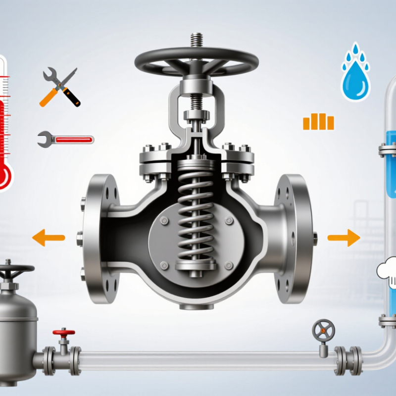
A pressure relief valve protects equipment when pressure rises beyond a safe limit. It opens automatically, releases excess fluid, and helps prevent vessel rupture. In practical terms, it acts like a controlled escape route. Boilers, compressed-air receivers, pipelines, and process vessels commonly need this protection. The valve must match the system’s pressure, temperature, and fluid.
Choosing one requires more than comparing connection sizes. Check the required set pressure, relieving capacity, operating temperature, and backpressure. The valve should discharge enough fluid to control the worst credible pressure event. Material selection also matters. Stainless steel may suit corrosive liquids, while other applications need different alloys or seals. Always confirm compatibility with the actual medium.
Installation details can change performance. A long, narrow inlet pipe may restrict flow. A blocked discharge line can create a dangerous condition. Qualified engineers should verify sizing calculations and applicable pressure-equipment standards. Maintenance teams should inspect the valve for corrosion, leakage, and a damaged spring. A valve may appear clean but still fail to lift correctly. That is easy to overlook. I would recheck the setting after major process changes, because an old calculation may no longer reflect real operating conditions. Regular testing, accurate records, and clear access make the protection more dependable.
Which Pressure Relief Valve Type Fits the Application?
How to Choose a Pressure Relief Valve?
Which Pressure Relief Valve Type Fits the Application?
Choosing the right pressure relief valve starts with the process, not the valve catalog. Identify the fluid, normal pressure, set pressure, temperature, required capacity, and discharge destination. A clean liquid system often suits a spring-loaded relief valve. It responds quickly and has a straightforward design. Gas and steam systems may require a safety valve with suitable lift and blowdown performance. Verify the operating range carefully. Small pressure changes can affect stability.
Pilot-operated valves can work well on large systems with steady pressure and high flow requirements. They offer accurate control, but dirty fluids may obstruct the pilot circuit. A rupture disk can provide rapid, non-reclosing protection, especially where a valve might react too slowly. It cannot be reset after activation. Backpressure also matters. Excessive backpressure may reduce capacity or cause unwanted opening. I have seen selections fail because discharge piping was treated as an afterthought. That detail can change the entire calculation.
Tips: Check certified capacity data, material compatibility, and installation orientation. Confirm the valve’s set pressure against the weakest protected component. Review real operating conditions, not only design values. If the process is unstable, consult a qualified engineer and test the complete assembly. A perfect datasheet does not guarantee perfect field performance.
How to Determine the Required Valve Size and Pressure Setting?
How to Choose a Pressure Relief Valve?
Choosing the correct pressure relief valve starts with the required relieving capacity. Identify the credible overpressure scenario, such as a blocked outlet, fire exposure, or thermal expansion. Each case may produce a different flow rate. Use the vessel’s maximum allowable working pressure as the primary reference. The valve set pressure must not exceed this limit. Normal operating pressure should remain comfortably below the set point, or the valve may simmer and leak.
Valve size depends on more than the connection diameter. Calculate the required mass flow using the fluid type, temperature, relieving pressure, and backpressure. Gas, steam, and liquid services require different sizing methods. Check the certified flow coefficient and account for inlet pressure loss. Excessive loss can cause unstable operation. Outlet piping also matters, especially when discharge backpressure may reduce capacity. I have seen oversized valves create poor control, while undersized valves fail to protect equipment. A quick rule of thumb is not enough.
Tips: Record every assumption. Confirm the vessel rating, operating range, fluid phase, and relieving scenario. Compare the calculation with recognized engineering standards and verified sizing data. Ask a qualified engineer to review the result, especially for fire cases or toxic fluids. Test the final pressure setting under controlled conditions. Small details matter. Temperature corrections, fouling, and installation orientation can change performance. My first calculation is rarely perfect, so I always review the process conditions before approving the valve size.
Which Materials and Performance Features Should Be Evaluated?
How to Choose a Pressure Relief Valve? Which Materials and Performance Features Should Be Evaluated?
Material selection begins with the fluid, temperature, pressure, and corrosion mechanism. A stainless steel body may resist moisture, yet chlorides can still damage its seat or spring.
NACE International’s IMPACT study estimated global corrosion costs at about 2.5 trillion annually, equal to 3.4% of global economic output. That figure makes compatibility more than a specification exercise. It affects maintenance budgets and plant safety.
Check the body, nozzle, disc, spring, and gasket separately. Wetted parts may require stainless steel, nickel alloys, or specialized elastomers. At high temperature, spring relaxation can change the set pressure. At low temperature, seals may harden and leak.
ASME Boiler and Pressure Vessel Code Section VIII provides recognized rules for pressure-relief device design and capacity certification. API 520 also addresses sizing, selection, and installation practices. These references should support engineering judgment, not replace it.
Performance evaluation should include certified set pressure, relieving capacity, blowdown, backpressure tolerance, and leakage control. Two valves with identical pressure ratings may behave differently during rapid pressure rise.
I would also examine test records, material certificates, and inspection intervals. A practical mistake is choosing the cheapest corrosion-resistant alloy without checking its actual process chemistry. Another is ignoring discharge piping loads. Field conditions are rarely perfect. The valve may face vibration, pulsation, fouling, or an unexpectedly cold startup.
How Should a Pressure Relief Valve Be Installed and Maintained?
A pressure relief valve should be installed by qualified personnel under the applicable pressure equipment code. Before installation, verify the valve’s set pressure, connection size, temperature range, and material compatibility. These details must match the protected vessel and process conditions. Keep the valve upright. Its inlet pipe should be short, clean, and large enough to prevent excessive pressure loss. Remove welding debris, scale, and protective caps before connection.
The discharge line must lead to a safe location and remain properly supported. It should not create back pressure beyond the valve’s approved limit. Never place an unauthorized isolation valve between the vessel and relief valve. Do not improvise. During commissioning, check for leaks, vibration, blocked outlets, and incorrect flow direction. A small leak may indicate contamination, damaged seating, or an unsuitable setting.
Maintenance should follow a documented schedule based on service severity, inspection results, and local requirements. Inspect corrosion, spring condition, seals, mounting bolts, and discharge piping. Test the valve using calibrated equipment, and record the test pressure, date, technician, and findings. A clean installation can still fail if records are poor. Field inspections often reveal neglected drains or painted valve labels. These small oversights deserve attention. Do not adjust the set pressure without proper authorization and qualified testing. If the valve has lifted repeatedly, investigate the underlying overpressure instead of simply resetting it.
How to Choose a Pressure Relief Valve?
How Should a Pressure Relief Valve Be Installed and Maintained?
The chart illustrates pressure relationships for a protected system with a 10 bar maximum allowable working pressure (MAWP). Normal operating pressure should remain below the valve set pressure, and the set pressure must not exceed the equipment MAWP. The 11 bar accumulated-pressure value represents a commonly used 10% overpressure reference for certain relief scenarios; the applicable design code and service conditions must always be verified.
Select the valve according to the required relieving capacity, set pressure, temperature, fluid compatibility, inlet and outlet piping conditions, and certified code requirements. Install it upright where practical, with an unobstructed inlet, adequately supported discharge piping, no isolating valve that could prevent protection, and drainage to avoid liquid accumulation.
Maintenance should include regular visual checks for corrosion, leakage, blockage, vibration, and tampering. Functional testing, inspection, and recalibration should follow the equipment manufacturer’s instructions, applicable regulations, and the site risk-based maintenance schedule.