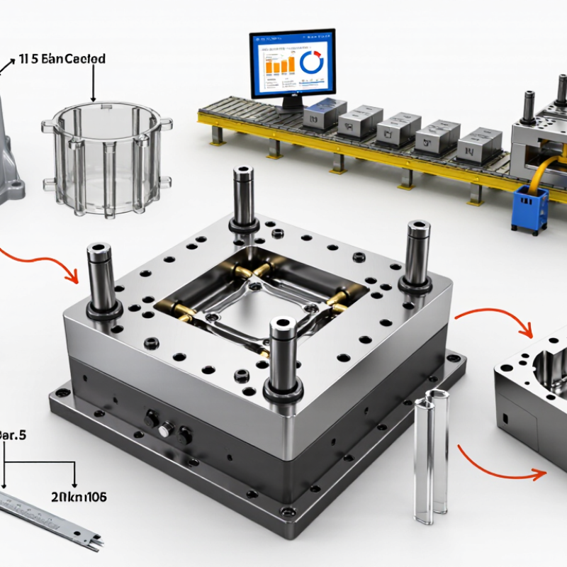
Choosing the right Injection Molding Die begins with understanding the part, material, production volume, and expected service life. A die that performs well for a simple polypropylene housing may fail with glass-filled nylon. Small errors become expensive.
An experienced tooling engineer examines wall thickness, draft angles, ribs, undercuts, and tolerance requirements before selecting the die structure. These details affect cooling speed, ejection force, cycle time, and surface quality. For example, uneven walls can leave visible sink marks near a thick boss. A practical review also considers hot runner systems, cavity numbers, steel grades, and maintenance access. The cheapest quotation may hide difficult repairs or short component life. It happens more often than buyers expect.
Reliable suppliers should provide clear drawings, steel certificates, trial reports, and measurable inspection results. Mold-flow analysis can reveal filling problems, but it cannot replace a physical trial. Watching the first molded parts is valuable. Check flash along the parting line, gate marks, warpage, and ejection damage under consistent lighting. Industry experience suggests that early design changes usually cost less than late modifications. Still, no selection method is perfect. Material batches vary, production conditions drift, and even a carefully reviewed die may need adjustment. A sound decision balances technical evidence, supplier capability, maintenance planning, and realistic production goals. That balance protects quality without treating every project as identical.
Injection molding dies, commonly called molds, shape molten plastic inside a cooled cavity. Their design affects cycle time, surface finish, part accuracy, and maintenance cost. The Plastics—The Facts 2024 report records 413.8 million tonnes of global plastics production in 2023. That scale makes efficient tooling increasingly important.
It starts there.
A cold-runner mold uses solidified channels that require trimming or recycling. It is often simpler and cheaper for moderate production volumes. A hot-runner mold keeps material molten inside heated channels, reducing runner waste and shortening cycles. However, it needs accurate temperature control.
Two-plate molds suit many basic parts, while three-plate molds can place gates more flexibly. Stack molds multiply output within one machine footprint. Insert and overmolding tools combine different materials or components.
The right type depends on geometry, resin, annual quantity, tolerance, and available press capacity.
According to the 2024 Plastics Industry Association Size and Impact report, plastics manufacturing supports more than one million jobs in the United States. That workforce also reveals a practical truth: tooling decisions affect operators, not only engineers.
I would not choose a die from price alone. A low-cost cavity may hide difficult cleaning, poor cooling, or fragile slides. Maintenance matters. Inspect cooling channels, vent locations, ejector access, and steel hardness before approval.
My first selection can still be wrong when demand changes. A pilot mold, measured cycle data, and a documented design review reduce that risk.
Choosing the right injection molding die starts with a precise product definition. Record the part’s material, dimensions, wall thickness, surface finish, and expected service life. Also identify tolerance zones, visible surfaces, assembly points, and areas exposed to heat or chemicals. These details determine cavity layout, cooling design, venting, ejection, and tool steel requirements. Production volume matters just as much. A short run may justify a simpler die, while millions of parts require stable cycle control and replaceable wear components. Cost is important, but downtime can quietly exceed the initial tooling budget.
Manufacturing objectives should be written beside product requirements, not discussed later. Set targets for cycle time, scrap rate, dimensional consistency, maintenance intervals, and acceptable tooling cost. Decide whether flexibility or maximum output matters more. Interchangeable inserts can support design changes, but they may increase upfront complexity. Automation can improve repeatability, yet it cannot correct poor part design. During reviews, request filling analysis and trial data before approving the die. Look for short shots, weld lines, sink marks, flash, and uneven shrinkage. Small defects often reveal larger process weaknesses.
A practical warning: specifications are rarely complete. I have seen teams overstate production volume and underestimate future design changes. That mismatch can produce an expensive die with limited value. Ask which assumptions are measured and which are guesses. Use validated material data, measured samples, and documented trial records. Document material variation and operator skill. Leave room for revision.
How to Choose the Right Injection Molding Die?
Choosing an injection molding die begins with the material, production volume, and part geometry. Hardened tool steel suits long runs and abrasive plastics. Pre-hardened steel can reduce machining time for moderate production. Aluminum offers faster prototyping, but it may wear sooner under repeated pressure. Material selection is not only a cost decision. It affects surface finish, cooling stability, and maintenance intervals.
Review the die design closely. Adequate draft angles help parts release without scuffing. Smooth transitions reduce stress around ribs, bosses, and thin walls. Gate location should support balanced filling and hide visible marks where possible. Cooling channels need even spacing around thick sections. Poor cooling creates warpage, even when the cavity looks accurate. Ejector pins must support the part without leaving damaging impressions. Small details matter.
Tips: Check the parting line with a real sample. Confirm steel hardness, shrinkage allowances, vent depth, and expected cycle time. Ask for a mold-flow review when the geometry is complex. Do not trust a perfect drawing alone. Production feedback may reveal a weak corner, a trapped air pocket, or an ejector mark that testing missed. A simple maintenance plan should include cleaning, lubrication, alignment checks, and inspection of wear areas.
| Selection Area | Option / Specification | Typical Material or Design Data | Wear Resistance | Corrosion Resistance | Thermal Performance | Recommended Application | Key Design Considerations | Relative Cost |
|---|---|---|---|---|---|---|---|---|
| Die Material | Pre-hardened tool steel | Typical hardness: approximately 28–40 HRC. Often supplied ready for machining without additional hardening. | Good | Moderate | Balanced heat transfer and dimensional stability for general-purpose molding. | Medium-volume production, automotive interiors, housings, and general engineering plastics. | Good machinability and reduced heat-treatment distortion; may require surface treatment for abrasive or corrosive polymers. | Medium |
| Die Material | Through-hardened tool steel | Typical hardness: approximately 45–60 HRC after heat treatment, depending on grade and processing. | Excellent | Moderate | High dimensional stability at elevated molding temperatures when properly heat-treated. | High-volume production, glass-fiber-filled thermoplastics, and components with demanding tolerances. | Requires controlled heat treatment, stress relief, and careful machining; harder material increases manufacturing time. | High |
| Die Material | Corrosion-resistant stainless tool steel | Typical hardness: approximately 45–56 HRC in hardened condition. Chromium content improves resistance to moisture and corrosive resins. | Good | Excellent | Stable performance in humid environments; thermal conductivity is generally lower than copper alloys. | PVC, flame-retardant materials, medical components, cleanroom tooling, and humid production environments. | Use polished surfaces, suitable venting, and corrosion-resistant cooling fittings where moisture or corrosive gases are present. | High |
| Die Material | Precipitation-hardening stainless steel | Typical hardness: approximately 35–50 HRC, depending on aging treatment and selected condition. | Good | Excellent | Good dimensional stability and corrosion resistance after controlled aging treatment. | Medical parts, optical components, corrosion-sensitive tooling, and molds requiring reliable polishability. | Plan machining allowances around heat treatment and aging; verify final hardness before polishing or texturing. | High |
| Die Material | Aluminum mold alloy | Typical hardness: approximately 90–150 HB. Thermal conductivity commonly exceeds that of tool steel. | Limited | Moderate | Rapid heat transfer can shorten cooling time and support fast prototype cycles. | Prototype molds, bridge production, low-volume parts, and large components with moderate pressure requirements. | Use generous radii, replaceable wear inserts, and appropriate surface treatment when molding abrasive materials. | Low to Medium |
| Die Material | Copper alloy insert | High thermal conductivity compared with conventional tool steels; hardness is lower than hardened steel. | Moderate | Moderate | Excellent local heat removal for hot spots, deep ribs, thick sections, and difficult-to-cool areas. | Localized cooling inserts in production molds where cycle time is limited by uneven heat transfer. | Use as an insert rather than a complete mold in high-wear locations; protect against erosion and galling. | Medium to High |
| Mold Structure | Two-plate mold | One primary parting line; generally uses a direct sprue or cold runner system. | Depends on selected steel and surface treatment. | Depends on selected steel and molding environment. | Simple cooling layout with relatively low pressure loss through the runner system. | Parts with straightforward ejection and a gate located on the parting plane. | Simple construction, lower maintenance burden, and lower initial cost; runner removal may be required. | Low to Medium |
| Mold Structure | Three-plate mold | Uses an additional parting system to separate the runner from the molded part automatically. | Higher maintenance demand at moving plate interfaces. | Depends on selected steel and operating conditions. | Longer runner paths can increase pressure loss and material waste compared with a two-plate design. | Multi-cavity parts or applications requiring centrally positioned or multiple point gates. | Allows flexible gate placement but requires careful alignment, opening-sequence control, and maintenance. | Medium to High |
| Mold Structure | Hot-runner mold | Heated manifolds and nozzles keep the polymer molten, reducing or eliminating cold-runner scrap. | Requires wear-resistant components around gates and shut-off areas. | Material-dependent; corrosive polymers require compatible hot-runner components. | Improves material efficiency but requires precise temperature control and balanced heating. | High-volume production, multi-cavity parts, thin-wall components, and applications with high resin cost. | Control gate vestige, heater layout, thermal expansion, startup procedures, and cleaning access. | High |
| Mold Structure | Stack mold | Multiple mold parting levels operate in one injection molding machine cycle. | High mechanical complexity increases the need for robust wear protection. | Material and environment dependent. | Requires balanced cooling across all levels to maintain consistent part quality. | High-volume production where machine capacity and floor space must be used efficiently. | Check machine platen size, mold height, opening stroke, ejection synchronization, and total mold weight. | Very High |
| Design Feature | Cooling channel layout | Channels should follow the cavity contour where practical; spacing and diameter must support uniform cooling. | Use corrosion-resistant channels or treatments when water quality is poor. | Strongly affected by coolant chemistry and maintenance. | Uniform cooling reduces cycle time, warpage, sink marks, and residual stress. | All production molds, especially thick-wall, high-shrinkage, or dimensionally critical parts. | Include baffles, bubblers, conformal inserts, flow measurement, and independent circuits for different thermal zones. | Medium to High |
| Design Feature | Venting system | Vents are commonly placed at the end of fill, parting lines, ejector locations, or other air-trap areas. | Vent edges may wear or become blocked by residue over time. | Use suitable materials and cleaning methods for corrosive molding compounds. | Effective venting reduces trapped-gas heating, burn marks, short shots, and filling instability. | Thin-wall parts, high-speed filling, flame-retardant materials, and complex geometries. | Vent depth must suit the polymer and process; excessive depth can cause flash, while insufficient depth traps gas. | Low to Medium |
| Design Feature | Ejection system | Common options include ejector pins, sleeves, stripper plates, air ejection, and hydraulic-assisted systems. | Hardened pins, guided plates, and replaceable wear components improve service life. | Corrosion-resistant components may be required for moisture-sensitive or corrosive applications. | Balanced ejection prevents deformation and reduces sticking-related heat buildup. | Parts requiring reliable automatic removal and controlled cosmetic surfaces. | Place ejectors on structurally strong areas; balance force, avoid thin walls, and provide adequate return and support. | Medium |
| Design Feature | Gate selection | Common choices include edge, pin-point, submarine, fan, tab, direct sprue, and hot-tip gates. | Gate inserts and shut-off surfaces may require higher hardness than surrounding cavity areas. | Choose compatible gate materials for corrosive or glass-filled polymers. | Gate size and location affect filling balance, shear heating, packing, and cooling behavior. | Selection depends on part appearance, wall thickness, flow length, material, and required automation. | Consider gate vestige, weld-line location, filling pressure, degating method, and fiber orientation. | Low to High |
| Surface Treatment | Nitriding, coating, or texturing | Surface modification can improve hardness, release, wear resistance, or corrosion resistance. | Excellent when matched correctly to the polymer and operating conditions. | Good to Excellent, depending on treatment. | Must withstand molding temperature without damaging dimensional accuracy or surface finish. | Abrasive polymers, high-cycle molds, difficult-release parts, and parts requiring controlled texture. | Confirm coating thickness, edge coverage, polishing compatibility, repairability, and treatment impact on dimensions. | Medium to High |
| Inspection Criterion | Dimensional stability | Evaluate shrinkage, thermal expansion, steel movement after heat treatment, and cavity-to-cavity variation. | Improved by stable steel, proper support, and controlled heat treatment. | Not directly applicable; environmental protection remains necessary. | Uniform mold temperature and balanced cooling are essential for repeatable dimensions. | Precision parts, optical surfaces, sealing components, and tight-tolerance assemblies. | Use mold-flow analysis, steel-safe design allowances, cavity pressure monitoring, and first-article inspection. | Medium to High |
| Maintenance Factor | Serviceability and replaceable inserts | Wear-prone areas such as gates, shut-offs, slides, cores, and cavity details can be designed as replaceable inserts. | Good when wear components are isolated and replaceable. | Improved when exposed components can be removed, cleaned, and treated separately. | Serviceable cooling plugs and removable inserts simplify cleaning and repair. | High-volume molds where downtime and repair cost have a major production impact. | Provide lifting points, inspection access, standardized fasteners, alignment features, spare inserts, and documented maintenance intervals. | Medium initially; lower lifetime cost |

How to Choose the Right Injection Molding Die?
Comparing Costs, Production Volume, and Maintenance Needs
Tool cost should follow production volume, not personal preference. A simple aluminum mold may suit prototypes or runs below 10,000 parts. Hardened steel usually costs more, but it can support hundreds of thousands of cycles. Recent market analysis from Grand View Research forecasts steady growth in injection molding demand through 2030. That growth does not justify overbuilding every tool.
Volume changes everything. A low-volume project may tolerate slower cycles, manual inserts, and easier machining. High-volume production needs balanced cooling channels, replaceable wear components, and automated ejection. A 2024 manufacturing cost study from Deloitte found that unplanned downtime can significantly increase total operating costs, especially in asset-intensive plants. Therefore, maintenance access deserves early design attention. Ask whether technicians can remove a damaged slide without dismantling half the mold.
Maintenance is often underestimated. It includes cleaning vents, checking alignment, polishing cavities, and replacing seals. Poor venting may create burn marks after thousands of shots. That repair can interrupt delivery schedules. ISO 9001-based quality programs also emphasize documented inspection and preventive maintenance, although implementation differs between facilities. My practical estimate may still be imperfect: a cheaper mold can become expensive when downtime, spare parts, and rejected parts are included. Get cycle-life evidence, maintenance records, and a volume-based quotation before approving the design.
Prototype aluminum molds generally offer the lowest initial cost and are suitable for small production volumes. P20 steel molds require more investment but support medium-volume production, while hardened steel molds provide the longest service life for high-volume manufacturing. Maintenance intervals are typical planning ranges and vary with material, part complexity, cycle time, and mold design.
Choosing an injection molding die manufacturer requires more than comparing prices. Review their experience with your material, part geometry, and expected production volume. A capable supplier should explain steel selection, cooling design, gate placement, and expected die life in practical terms. Ask for recent project examples, inspection records, and references from comparable applications.
Quality claims need evidence. Confirm whether the manufacturer maintains a certified quality management system, such as ISO 9001, and verify the certificate with the issuing body. Request material certificates for die steel, heat-treatment records, dimensional inspection reports, and controlled revision documents. Before approval, require a trial sample from the actual die. Check critical dimensions, surface finish, flash, warpage, and cycle consistency. A clean sample is useful, but one successful shot proves little. Repeated trials reveal more.
Tips: Visit the facility if possible. Watch how technicians measure cavities, store components, and record corrections. Ask who owns the inspection data and how changes are approved. Clarify maintenance support, spare inserts, response times, and warranty limits in writing. Do not accept vague promises. I have seen projects delayed because a small venting issue was treated as minor. It was not. Leave time for design changes, because even a well-reviewed die may expose weaknesses during production. One overlooked detail can become thousands of rejected parts.
Phone: (256) 845-1255 or (256) 845-4493
Fax: (256) 845-1321 or (256) 845-4468
© 2025 Heritage Wire Harness, LLC